Inventor Basics - Ch 2 - The Base Features
Inventor Basics – Chapter 2 – The Base Features
With our opening chapter covering the Sketch environment and a few best practices, let’s create our first solid model(s).
We’ll cover the processes and tips of creating different base features using the Extrude, Revolve, Sweep, Loft, Coil and Rib commands.
These basic commands do offer a lot of options, yet users tend to either forget them or in their rush to get the model done, they gloss past them, not realizing they could be generating even more work for themselves.
Let’s take a look at the more common/useful ones.
Extrude
The Extrude command is probably the most commonly used base feature.
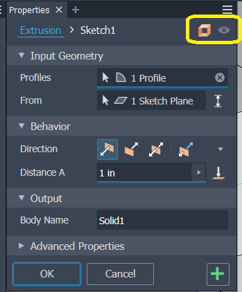
Selecting the Extrude command, a pop-up dialogue menu offers a list of your options available.
At the top right corner of the menu, notice your options of creating a solid (default) or a surface output for the command as well as the preview of what the result will be.
Note: This preview is extremely helpful, especially when creating complex or difficult to envision features. If the feature operation has a chance to fail, the preview will either show in red or not show at all. This comes in very handy for features that could take a lot of processing and time to complete, just to end up failing for some reason. If and when you see such a preview, back out of the command and reinspect your profile and or what you are attempting to process.
· Input Geometry section: Since there is only one closed sketch in this example, Inventor automatically selects it. If there were multiple closed loop sketches, you can mouse over and select the appropriate loop(s) to complete the command.
· Behavior section: Here are the options for the direction of the Extrude. From left to right:
o Default (positive direction)
o Flipped (negative direction)
o Symmetric (equal in both positive and negative directions)
o Asymmetric (unequal distances)
o Distance A: Distance(s) (depending on option selected)
o The “To” icon (this allows you to select an entity to extrude to (this can be very helpful if you want the extruded feature to always stop at a specific face for example without limiting its distance with a parameter. This is an example of modeling to design intent.
· Output section: Here you’ll given the option to name the feature for easier identification in the tree structure
Note the arrow icons to the left of each heading, selecting these toggles the expanded menu. In this case the Advanced Properties section where you can specify a Taper among other options.
At the bottom of the menu, you have the “OK” to accept the options and create the extrusion feature, “Cancel” to cancel the operation and the green “+” button to create the feature with the current options and leave the menu open to create a new extrusion feature.
Lastly, depending on the menu, the “hamburger” or “stack” icon in the upper right offers various command related settings as well:
Revolve
The Revolve command is one that does stump beginners at times. This command requires a little forethought at the sketch stage. For example:
In sketch mode, if the profile loop of the desired feature is at a distance away from the centerline/axis of the revolve, the result creates a “through hole” in the center:
Whereas if the profile is in line with the centerline/axis of the revolve, the result is a solid feature:
Keep in mind if the profile crosses the centerline/axis of the revolve, the command will fail as the revolve will in essence fold onto itself.
Sweep
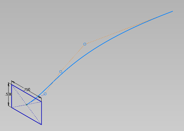
The Sweep command takes a bit more upfront work than the Extrude and Revolve commands as it requires at least two sketches, one for the profile and the other for the guide of the sweep.
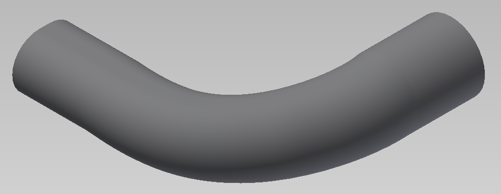
Select the Sweep command and select the options needed for the result desired. This may take some trial and error to find the ideal result.
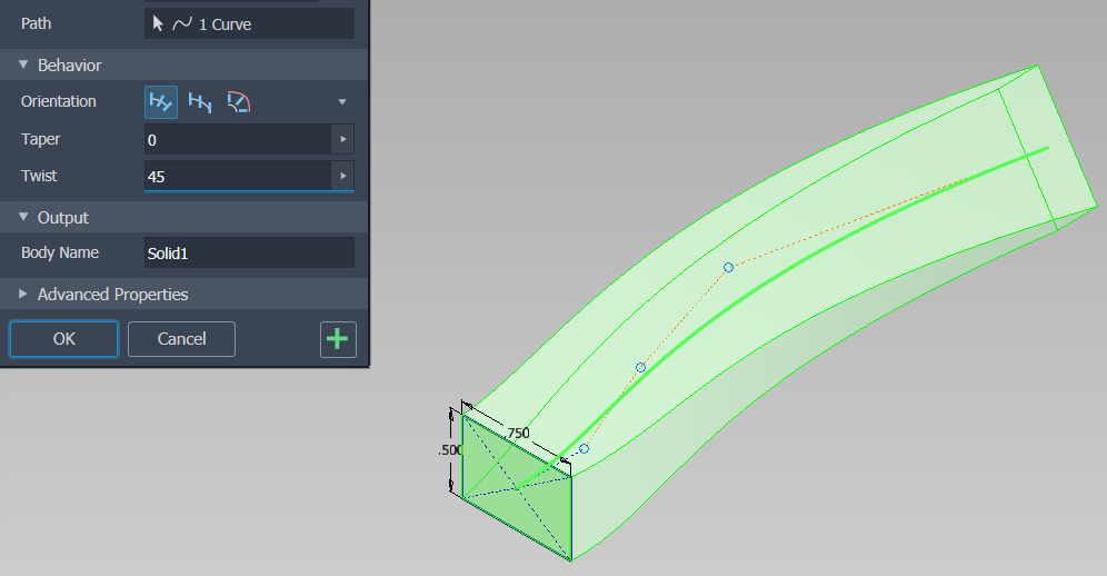
Note: You can select to sweep the profile with a Taper (in degrees):
And/or a Twist (in degrees):
Loft
The Loft command is hands down one of my favorites in the sense it can get you some crazy results and thus one must use extra caution when working with it. Otherwise, as Doc Brown says…
© Universal Pictures
“You’re about to see some serious ****!
Lofting is when you want to create a transition from one profile to a different profile or more.
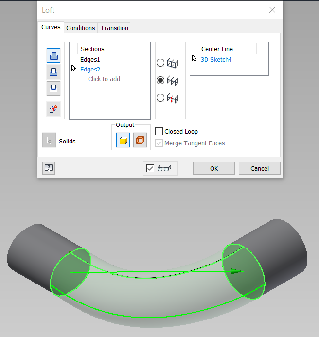
For example: Here we have a straight section of an oval type shape on the left that needs to loft around a curve and blend into the circular shape to the right.
In this case you have the oval face, a centerline guide at the top and the circular face it must transition to. Just three entities needed here, giving the below result:
Hey look, a smiley face. Who says you can’t have fun writing these blogs?
Now let’s look at how we got here and a few other options with the Loft command.
There are numerous options available to assist you in getting the result you need. Like the Sweep command, this may require some trail & error to get the optimal result (Keep in mind, too much of a good thing (rails/guidelines) can bring bad results. Less can be more in some cases).
Let’s cover a few.
The Sections window is where the selected profiles will be listed as you add them. You can select multiple by clicking on the “click to add” area. Select the first face/profile, select “click to add” and select the second face/profile as shown below: (note the preview)
In the middle of the menu you’ll see three guide rail options.
They are Rails, Centerline and Area. In this case, we want to be able to control the transition to follow the curved guideline, we need to select the Centerline option and then select that centerline guide: (note how having the Preview option active can save you time and effort)
Let’s not forget the common icons at the far left, top (Join); middle (Cut) and at the bottom (Intersect), we’ll see these in numerous other commands, and we’ll cover how each can be used and when. For now, we’ll stay with the Join option for some brevity in this article.
In the above example, we used a very simple and straightforward process. If we needed more control on the resultant loft, we could add and select multiple guidelines/rails. You also have condition options on the Conditions tab that’ll allow you to control the smoothness of the loft.
Let’s look at another example, this one you may have seen from Autodesk Help files, it’s a great example:
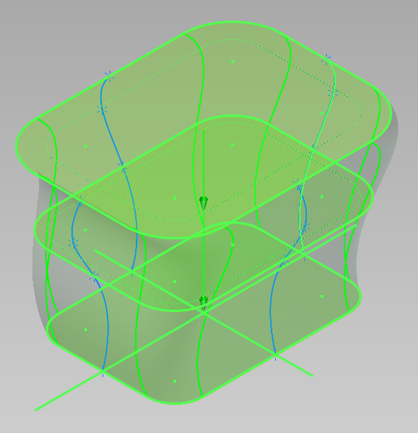
Here we have 3 profile sketches and 4 guides/rails. Note the guides are drawn in a 3D sketch which we will cover at a later writing.
Simply selecting the 3 profiles from top to bottom results in a basic loft between each as such:
You can see the loft is not following the guide rails as desired.
By selecting the “Rails” option in the middle of the menu, then selecting each Rail, you’ll get a preview of how these will control the loft:
· Back Rail selected
· Back and Front Rail selected:
· Side Rails selected: (finished command)
Coil
Much like the Revolve command, Coil needs a sketch with a profile and an axis entity to revolve the coil around.
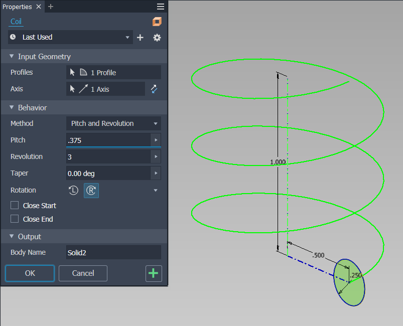
Activating the Coil command, Inventor automatically selects the profile as it’s the only closed loop in the sketch. Since I have two entities of a centerline style (done on purpose), you’ll need to select which one you want as the axis or revolution. In this case, of course we will select the vertical axis line:
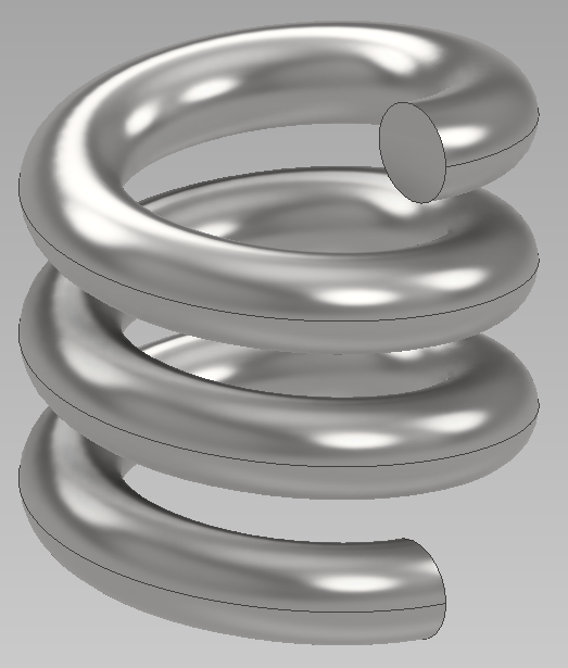
You should then see a preview of the coil based on the inputs in the Behavior section. Here they are set at 1 inch for the Pitch and one instance of rotation. Let’s change that to a pitch of .375” and 3 instances of rotation:
You can also set a Taper, change the Rotation direction as well as setting a closed Start and/or End:
Rib
The Rib command is another “fun” command. The Rib command is two commands in one. First, its namesake, the Rib. Ribs are support features. They are parallel to the sketch plane and can use an open or closed sketch loop.
How to create a Rib feature: Create an open or closed loop sketch on the desired plane (in the example below I selected the mid-plane of the component).
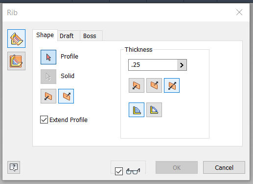
Finish the sketch and select the Rib command. The following pop-up menu opens:
On the Rib command menu, In the upper left, you have the choices of Normal to the sketch plane (top icon) and Parallel to the sketch plane (bottom icon). For a Rib, we’ll need to select the Parallel icon.
Notice how the menu options have changed.
Next, select the sketch profile you’ve created. Select Direction 1.
On the Thickness section, Input the desired thickness, select the direction of the feature (for this example I will select the Symmetrical option, and then finally, select depth of the rib.
· To Next terminates the feature on the next face
· Finite terminates the feature to a specific distance (enter the desired distance)
With the Preview option active, I can see exactly how the rib will look. Select OK to finish the command.
Your Rib feature is now complete.
The second portion of this command is to create a Web. Webs are also support features, but Webs are normal to the sketch plane.
Select the Normal to the Plane option and you’ll notice Inventor has auto selected the sketch entity and previewing the resultant feature. Set the Thickness, Directional and Termination options as you would for a Rib. But with a Web, notice the extra tabs on the menu for adding in a Draft and or a Boss.
Once all desired selections are made, select “OK” to finish the feature and close the dialogue box.
Your Web feature is complete.
And with that, you now are familiar with creating your first solid feature. I recommend playing around with the different options and getting comfortable with them. Push them to the limit and see what they can handle.
Publishing Note: Due to the upcoming holidays in the US of A, our next chapter will be a much shorter write-up covering how to create secondary features to your solid model.
Until then, Happy CADding!


