Inventor 101 - Section Views
Section Views are used to display the component or components in a cutaway style to clarify internal portions of the component(s). To create a basic Section View:
Step 1: With the drawing file open, select the Section View icon from the Ribbon menu’s Place Views tab, Create panel:
Step 2: Select the view in which you want to section. This makes the view active for the pending section cut line, which is a sketch entity (more on this later).
Step 3: “Draw” the sectioning line to represent the “cut” path of the component(s).
Step 4: Right-click the mouse (RMB), select “Continue”.
Step 5: Set/Select the options as required in the Section View dialogue box.
Step 6: Select the placement location for the view using the left mouse button (LMB).
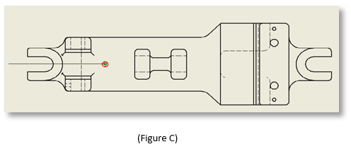
Key Hint #1 on Section Views – positioning the mouse over an entity endpoint, midpoint, center, etc. will give you a green glyph (Figure A & C), pulling off that will give you a dotted line (Figure B) for guidance and placing the section cut location with such, will line the cut with that point (Figure D & E).
Key Hint #2 on Section Views – Do not create a view-based sketch line to locate your section view cut line. The Section View command creates its own sketch in the process. Place the section View cut line by “eyeballing” it, then once the command is done, RMB on the Section View cut line and select Edit. This will put you into Sketch mode where you can now constrain the cut line to the exact location you need.
Always constrain your section cut line so that when edits of the components happen, the section cut will update accordingly.
Happy sectioning!


