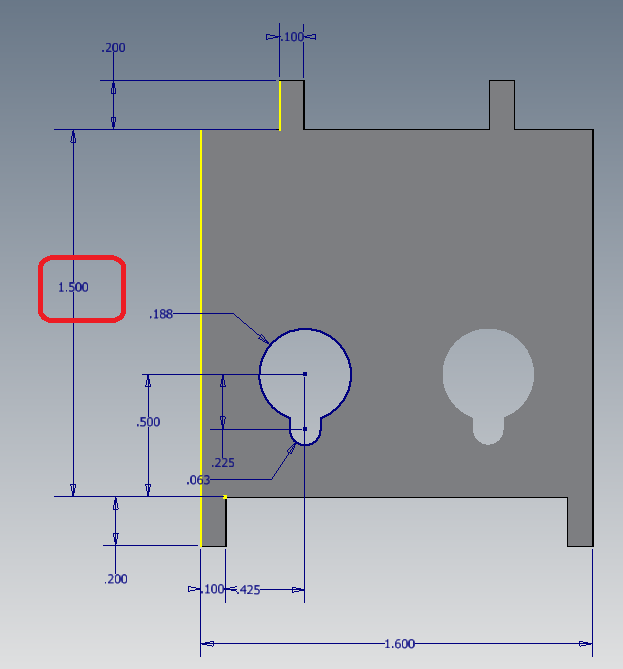
Inventor – Model Dimensions vs User Dimensions
Personally, if I could spend my entire working day creating the 3D model, I’d be a happy camper. That’s what I’ve always loved doing in CAD whether it be in Inventor, SW, Pro/E, CADDS5i, Catia…it doesn’t matter, I just love to create 3D solid models.
But on the other side of the fence, I eventually need to document that model. For me, the less time I have to spend on the detailing side, the better. Don’t get me wrong, I don’t mind creating drawings, I would just rather be in the 3D realm instead.
So with that in mind, anything I can do to shorten my time in the drawing, the better.
One of these tactics is the use of Model dimensions in drawings.
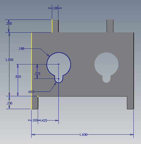
What are Model dimensions? Model dimensions are created during the sketching process of creating the 3D model. So, consider if you’ve already input these dimensions on the 3D model, why input them again on the drawing side? You should never double dimension on your drawings, isn’t this basically the same deal? It is in my mind.
There are three ways of bringing the Model dimensions over into the drawing view.
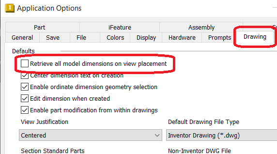
1. Application Options > Drawing tab > Select the “Retrieve all model dimensions on view placement”:
This will bring over all the Model dimensions that are planar to the pending view into said view on, you guessed it, View Placement. Since you are setting this in the Application Options menu, this will happen for ALL views created in Inventor from this point on.
For more control on which views this practice takes place, you’ll want Option #2 below.
2. When placing the view > Recovery Options tab > Select the “All Model Dimensions” check box:
This gives you the same results as in Option #1 above but allows you to decide which views you want the Model dimensions to come in on as opposed to the all-or-nothing option.
If you want to bring in the Model dimensions for a view that has already been placed, you’ll want to use Option #3 below.
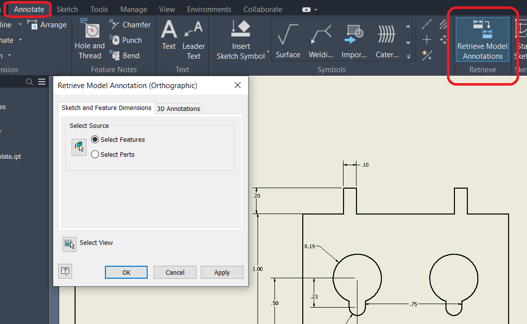
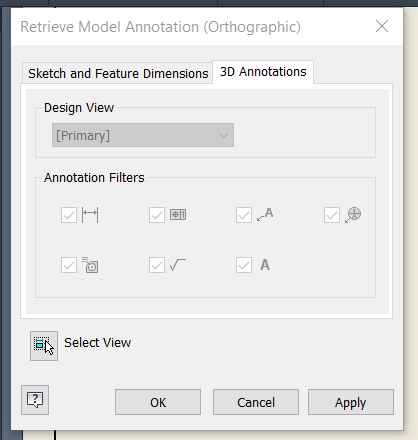
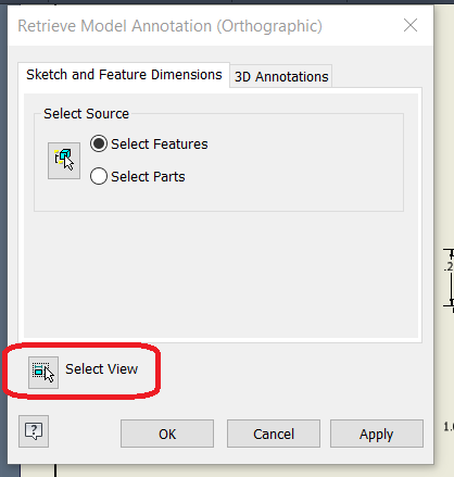
3. After the view has already been placed: Annotation tab > Retrieve Model Annotations icon:
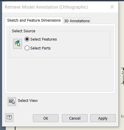
Here, you have a few options to select, depending on your needs.
· On the Sketch and Feature Dimensions tab, you can select the Source of the dimensions you want to bring over (per Feature or per Part)
· On the 3D Annotations tab, you can select the Design View and apply Annotation Features to include/exclude items like Feature Control Symbols (GD&T), Labels, Weld Symbols, Text, etc.
· Finally, if and when you have multiple views already set on the drawing, you have the option to select a specific view with the “Select View” button near the bottom of the pop-up menu
A few notes:
· In Orthographic views, only those dimensions that are on a plane parallel to the view are displayed.
· In Isometric views, all dimensions are available for selection.
· Model dimensions can be used only once per sheet
o (a Double dimensioning preventative)
· You typically include the model dimensions on the first/base view in the drawing as this is more often than not, the main view
· Subsequent projected views display only those model dimensions that did not display in the base view
o To show a specific Model dimension in another view, remove the dimension from the view it currently resides in, and retrieve it in the desired view.
· Use Model dimensions to populate most of your needed dimensions, then add User dimensions as needed to fully document the part.
Editing with Model Dimensions:
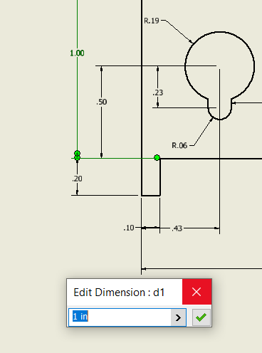
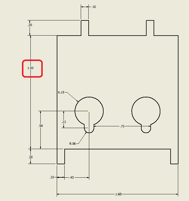
One of the best aspects of using Model dimensions is that you can edit the 3D model while in the drawing, without having to open the model file. Simply edit the Model dimension in the drawing view and the model is updated automatically.
Right-click on the dimension and select “Edit Model Dimension” from the pop-up
Input the desired size in the edit dialogue box, hit Enter.
I would suggest only doing minor edits to the model in this way. If you have significant changes or multiple dimensions to be edited, do such in the 3D model instead. This way you’ll be able to see and address any collateral issues the changes may affect.
To change the dimension tolerances, right-click in the edit box, and then select Tolerances.
CAD Admin Note: If you did not select the option to edit Model dimensions in drawings when you installed Autodesk Inventor, this option is unavailable. It is also unavailable when the selected dimension is a drawing dimension.

